In any scene, realism or artistic, one important effect remains constant throughout to ensure the viewer has a sense of depth in the area. That effect is shadows. Shadows are a nightmare for graphic developers in the sense that there is yet to be a "perfect" solution to them. Nevertheless for every technique out there there are workarounds to counter all the problems that may occur. Here we will look at Two-Pass Shadow Mapping - the popular method for generating shadows in a dynamic and real-time environment.
The Pros
Two-Pass Shadow Mapping is possibly the most efficient method of generating convincing shadows in a 3D scene. Requiring only one extra pass to obtain a depth map no additional shaders are required and only one additional texture lookup to compare depths in the lighting pass.
The Cons
When used in tandem with complex shaders the render function may end up being bloated with many passes if not properly managed. It also has a lot of issues that will need to be worked around to obtain the desired results. This means additional calculations are required.
The Code
So how does two-pass shadow mapping work? A fragment in shadow is one that is occluded by the incoming light from a light source. The easiest way to check this is by comparing the depth of a fragment between the point of view of the light source and the point of view of the camera. If an object is closer to the light source than the current fragment that means the object is occluding the light and is therefore in shadow. Diffuse and specular light are then removed from the fragment, leaving only the ambient contribution.
(Please note code comments are removed from these snippets)
glGenFramebuffers(1, &shadowFBO);
glGenTextures(1, &lightSpaceDepth);
glBindFramebuffer(GL_FRAMEBUFFER, shadowFBO);
glBindTexture(GL_TEXTURE_2D, lightSpaceDepth);
glTexImage2D(GL_TEXTURE_2D, 0, GL_DEPTH_COMPONENT24, 1024, 1024, 0, GL_DEPTH_COMPONENT, GL_FLOAT, NULL);
glTexParameteri(GL_TEXTURE_2D, GL_TEXTURE_MIN_FILTER, GL_LINEAR);
glTexParameteri(GL_TEXTURE_2D, GL_TEXTURE_MAG_FILTER, GL_LINEAR);
glTexParameteri(GL_TEXTURE_2D, GL_TEXTURE_WRAP_S, GL_CLAMP_TO_EDGE);
glTexParameteri(GL_TEXTURE_2D, GL_TEXTURE_WRAP_T, GL_CLAMP_TO_EDGE);
glBindTexture(GL_TEXTURE_2D, 0);
glFramebufferTexture2D(GL_FRAMEBUFFER, GL_DEPTH_ATTACHMENT, GL_TEXTURE_2D, lightSpaceDepth, 0);
glDrawBuffer(GL_NONE);
glReadBuffer(GL_NONE);
if (glCheckFramebufferStatus(GL_FRAMEBUFFER) != GL_FRAMEBUFFER_COMPLETE)
printf("Shadow FBO is incomplete\n");
glBindFramebuffer(GL_FRAMEBUFFER, 0);
To start, we generate the framebuffer to store our depth map from the lights point of view at startup. Unlike the standard framebuffer object we have been using only the depth attachment is generated, using the depth component as its source as opposed to an RGB(A) result. Here I am using 16-bit precision for the depth map which should be more than enough to correctly sample the depth. More complex scenes with a higher z-far frustum may need 24-bit precision but in the end this is just a small optimisation.
Instead of the application resolution the framebuffer uses a shadow map resolution which is typically squared. 1024x is a good balance for quality and speed. Larger resolutions will be more accurate but will ultimately use more DRAM and slow the texture lookup.
One more thing to note is that we explicitly define glDrawBuffer and glReadBuffer to GL_NONE as we are not drawing our scene, only obtaining the depth values. This is important as a framebuffer needs at least one colour buffer to be considered complete so doing this will ensure completeness. You can double check as always with glCheckFramebufferStatus.
shader *pList = ShaderInfo.getList();
glViewport(0, 0, shadowRes, shadowRes)
glBindFramebuffer(GL_FRAMEBUFFER, shadowFBO);
glClearColor(0.0, 0.0, 0.0, 0.0);
glClear(GL_COLOR_BUFFER_BIT | GL_DEPTH_BUFFER_BIT);
glEnable(GL_DEPTH_TEST);
glEnable(GL_CULL_FACE);
glCullFace(GL_BACK);
glUseProgram(pList[numShader].program);
mathLib.orthogonal(projMatrix, -10.0, 10.0, -10.0, 10.0, -10.0, 10.0);
mathLib.lookAt(viewMatrix, 0.0, 0.0, 0.0, 0.0, 0.0, -1.0, 0.0, 1.0, 0.0);
mathLib.translate(tranMat, 0.0, 0.0, -4.0);
mathLib.scale(scaleMat, 1.0, 1.0, 1.0);
mathLib.rotate(rotMat, angle, 0.0, 1.0, 0.0);
mathLib.makeModelMat(modelMatrix, scaleMat, rotMat, tranMat);
mathLib.multMatrix4x4(lightMatrix, projMatrix, viewMatrix);
glUniformMatrix4fv(glGetUniformLocation(pList[numShader].program, "modelMatrix"), 1, GL_FALSE, modelMatrix);
glUniformMatrix4fv(glGetUniformLocation(pList[numShader].program, "projectionMatrix"), 1, GL_FALSE, projMatrix);
glUniformMatrix4fv(glGetUniformLocation(pList[numShader].program, "viewMatrix"), 1, GL_FALSE, viewMatrix);
glBindVertexArray(objLoad.VAO);
glDrawArrays(GL_TRIANGLES, 0, 278781);
glBindVertexArray(0);
Now that we have the framebuffer object ready we add the pass to the render function. Again this is very similar to the normal pass with only a few minor differences...
Since the shadow map resolution will be 1024x the viewport also needs to be set as such to avoid any errors such as stretching or culling.
Right now we are looking at a directional light. This is a light that has no position and casts light equally across the whole scene in one direction. This makes it easy to model shadows as the light space view only needs to look down this direction onto the scene. Since it is modeled infinitely far away we need to choose a position up this direction vector to act as the view space position. Exactly where doesn't matter as long as it is looking into the scene.
You may be wondering why it doesn't matter where the position is. That is because for a light that is technically infinitely far away such as sunlight all light rays are following the exact same direction. So the projection of the camera will be orthogonal, not perspective, and with orthogonal view it doesn't matter how far or near you are to an object as the result will be the same. Additionally, directional lights do not attenuate as there is no distance. For this example the light is looking down the Z axis, the object is at (0, 0, -4) so the light is at (0, 0, 0).
Lastly we generate a light space matrix by multiplying the projection matrix with the view matrix. While not used in this pass it will be important in the lighting pass for comparing depths.
float shadowing(vec4 lightSpaceFragPos, float NdotL)
{
vec3 projCoord = lightSpaceFragPos.xyz / lightSpaceFragPos.w;
projCoord = projCoord * 0.5 + 0.5;
float closestDepth = texture(shadowMap, projCoord.xy).r;
float currentDepth = projCoord.z;
float bias = max(0.05 * (1.0 - NdotL), 0.005);
float shadow = currentDepth - bias > closestDepth ? 1.0 : 0.0;
return shadow;
}
The vertex shader for the shadow pass is a simple pass-through shader using the projection, view and model matrices to set the position of the object into the correct space in relation to the camera. The fragment shader consists of an empty main function as we do not need to draw or output anything. Once this is all done the program will automatically generate the depth component and store it to the shadow FBO's depth attachment texture.
In the lighting pass we set everything back to normal and now pass the new depth texture and the light matrix to the shader alongside everything else.
Now in the fragment shader we create a new function called shadowing, returning the result as a multiplier for specular and diffuse contributions, leaving ambient light as our shadows. The core of this function is relatively straightforward. Remember we want to compare depth values between the cameras view and the lights view, this means getting the vertex position in screen coordinates. So to start, we need the texture coordinates for the light space in NDC, or normalized device coordinates. When an object is in clip space (M * V * P) its X, Y and Z coordinates are within the range -W to +W. Ideally we need the coordinates to be within the range of -1 to +1 so this is all a matter of dividing by the W component. We have seen this before when performing Parallax Occlusion Mapping.
Since we are sampling a texture that is currently in the colour range of 0 - 1 the NDC needs to be scaled accordingly. This is done by multiplying by 0.5, then adding 0.5. Now our -1, 1 coordinate range is 0, 1.
You may now be thinking that the light was created with an orthographic projection, therefore the W component is always 1. This is true and this line is primarily for compatibility with perspective projection lights which I will go into a little later. Always better to be safe than sorry.
Next we obtain the closest depth from the light space view by doing a texture lookup, using the X and Y components as the texture coordinates. We then get the current depth by using the Z component.
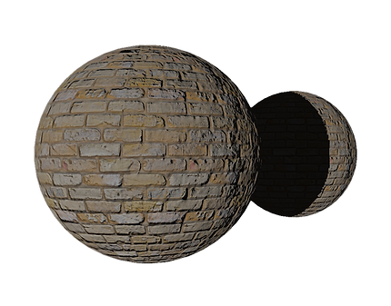
While the comparison is as simple as simple as checking whether current depth value is higher than the closest depth value doing so would bring us to our first issue of the imperfect shadow technique: Shadow Acne.

Shadow Acne
The above image shows one form of shadow acne. It can also be seen as pixel-thick shadow lines or dark artifacts across the light areas of an object. This is ultimately an issue with the shadow map resolution and the way it relates to how the depth lookup is sampled. Instead of raising the resolution which will lead to more texture memory being used and the problem only being fixed in certain situations (Think of a scene that stretches miles back and the texel size for the distance details) We can instead include a bias to the current depth value. This ensures every ray stops just above the ground level and is therefore all out of shadow when it should be. This bias only needs to be an extremely small number, as too large will result in noticeably offset shadows.
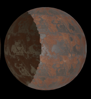
A flat value isn't always enough, however, and this is where our final line comes into play. Imagine a sphere in the light. With the fixed bias value only fixing issues in one direction the acne can still occur as the surface curves into grazing angles. So to ensure no acne is present in the scene it is better to change the bias amount based on the direction of the surface normal in relation to the light: NdotL. This is perfect as now there is a stronger bias at grazing angles whilst maintaining a closer bias wherever it can be used. Win/Win!
Peter-Panning
A second issue with the shadow mapping technique we have already averted but since mentioning it it is worth educating about. Peter-panning is the issue where an objects shadow is noticeably detached or offset from the object itself. This can be encountered and solved in a few ways. Firstly, as mentioned, setting the depth bias too high will result in Peter-Panning.The fix for this one is simply to reduce the offset as much as you can afford to.
If you look back I had already applied the most impactful fix to the issue by enabling front face culling in the shadow pass. Front face culling offers a more accurate depth map as the back side is what will be technically casting the shadows therefore its depth values are a closer and better option. This is not to say back face culling is a bad option however as it's not necessarily wrong and it definitely has its benefits. Imagine an object with no back face such as a floor plane, or an object that has an opening facing away from the light source. These will both affect the shadowing when front face culling. Front face culling will also not automatically shadow the surface of an object facing away from a light source, so keep that all in mind.
Finally Peter-Panning can occur when objects are simply too thin. Due to the resolution of a map the edge of a wall plane may show a "gap" where shadowing should occur. To fix this you should make sure objects in your scene are relatively thick.
PCF
One more problem we can expect to see is the effects of a lower resolution shadow map on a high resolution image: Aliasing.
Of course the simplest solution would be to just up the shadow map resolution which will remove or reduce problems with aliasing. But this will also bloat texture memory usage and heavily impact performance due to texture lookups in the shadowing function. We need to artificially anti alias the shadows to make them more acceptable in our scene. The advantage to this is that the anti aliasing also causes a little blur, resulting in soft shadows which look much nicer and more realistic. This process is called PCF or Percentage Closer Filtering.
PCF is about sampling the pixels around the current fragment to obtain a smoother blend between light and shadow. It is by no means the only or best option when fixing the aliasing problem but it is commonly used in real time applications. It may be worth experimenting with other sampling methods to see what works best with your scene.